Shift of resonant frequency in biological piezoelectric sensors

Shift of resonant frequency in biological piezoelectric sensors

Monitoring frequency shift using SinePhase Impedance Analyzer

Here, we examine the principles of how biological piezoelectric sensors and impedance analyzers can be used to detect changes in resonant frequency, including some practical applications and key aspects of using the technique.

Impedance analyzers have been used on a commercial basis and increasingly for biological applications since the 1980s. The techniques are relatively easy to learn and use, while equipment has also become increasingly portable and cost-effective due to technological advances over recent decades.

Impedance analyzers are used to measure static resistance and dynamic (or complex) impedance, whether the measurement is between connections of an electrical device under test (DUT) or between two or more points on a material that is under analysis.

In biological applications, electrical impedance depends on the level of opposition to the flow of electrical currents through the body or sample tissue(s) being measured. In humans, impedance may be measured from the wrist to opposite ankle, using up to four electrode sensors and a very low current of between 1-10 microamperes. The results can then be interpreted to gauge various medical criteria such as total body water (TBW) or changes in cellular structure, particularly through cellular surface characteristics.

Biological sensors are different from standard electrical sensors in that the resonant frequency changes are caused by cells reacting with and adhering to a differently coated surface. This adherence will increase the biomass, which will lead to decreased resonance and, therefore, a change in the resonant frequency. This principle is used in quartz crystal microbalance (QCM) systems.

8-channel monitoring of frequency shift using a SinePhase Impedance Analyzer
8-channel monitoring of frequency shift
using a SinePhase Impedance Analyzer

A QCM measures changes in density or film thickness (such as those caused by cellular surface deposits) within a certain area. A quartz crystal resonator generates various frequencies and then the changes in the response received from the tissue or sample are recorded. In addition to the resonator, the system also includes a quartz crystal sensor within a temperature-controlled mounting, as well as an electronic controller that monitors the frequency response over time.

Modern techniques allow QCMs to be used with liquids, giving precise results and therefore very effective for determining the affinity of proteins and other molecules to surfaces with defined characteristics. This methodology means that polymers, viruses and other biomolecules including bacteria and pathogens can be detected and investigated.

Apart from measuring the resonant frequency, another characteristic known as the dissipation factor can also be determined as part of the analysis process. Dissipation factor is related to frequency response bandwidth and gives an indication of the viscoelasticity of the sample being examined. Over recent years, improvements in crystal design, transducer engineering and the measurement of very short time intervals have combined to improve the accuracy of this technique.

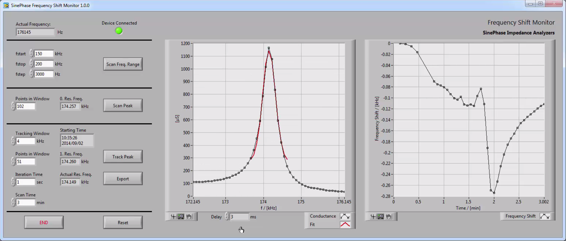
For analyzing the resonant frequency and any changes over time, an impedance analyzer is necessary. The standard analyzer software measures the conductance and its peak (i.e. resonant frequency) over the frequency range in question, using the software fitting tool and a single measurement sweep.

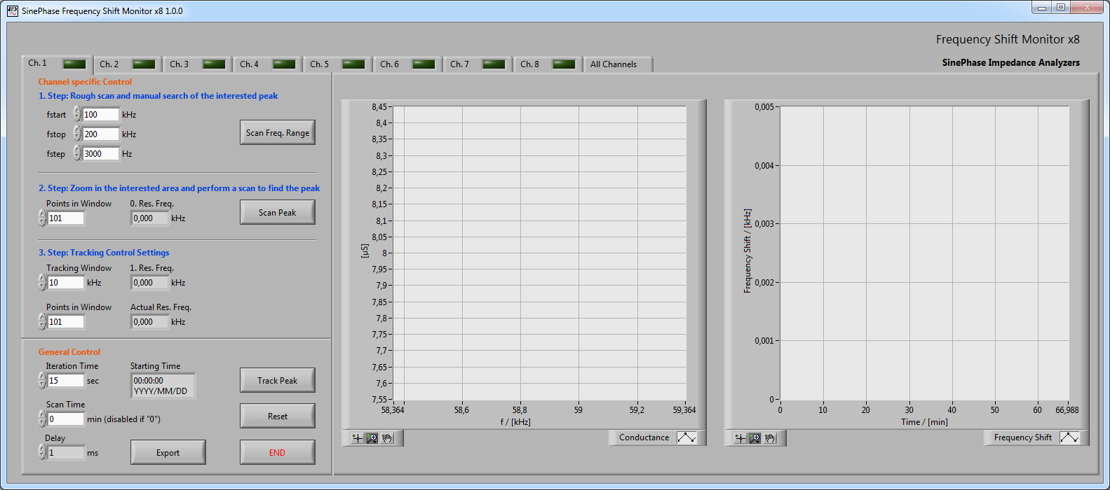
This standard measurement can be extended so that the resonant frequency value is tracked continuously and displayed over time. This is known as a frequency shift monitor and an example can be seen in the example picture on this page as well as in the video section area. This tracker solution or a similar configuration can be implemented for your project through a separate customized systems project. Of course a multi-channel solution (using eight channels, for instance) is also possible if a parallel frequency shift tracking system is needed, such as the shown example picture.


Customized Systems

At SinePhase, impedance analysis technology is not limited to a standard configuration; our products can be customized and are available with bespoke implementations and options to suit your requirements. Our experienced specialists will work with you to specify, design and manufacture customized hardware solutions that are based on our successful platform.

Extra functionality enables additional analysis with just a few keystrokes and gives quick indications of significant information including Q factor and half-value-bandwidth. Additionally, the extra correlation tool calculates and plots graphs of frequency shifts to illustrate current and earlier measurements and highlight any differences.

With our customized software, your individual analyzer system can be best adapted to your application environment, with performance parameters optimized through:

  • parallel or multiplexed multi-channel inputs.
  • tailored frequency range(s).
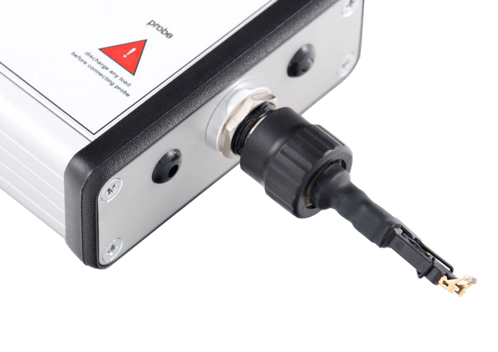
  • customized adapters and connections.
  • tailored measurement accuracy for specific impedance magnitudes.
  • seamless integration of SinePhase hardware and software into multifunctional test configurations and rigs.


If you wish to discuss your requirements or require further information about customized biological measurement solutions, please contact us – we will be pleased to help.

In this section you find following video (just scroll down) regarding monitoring of resonance frequency shift.

  1. Monitoring frequency shift – SinePhase Impedance Analyzer

1. Monitoring frequency shift - SinePhase Impedance Analyzer

Analyzing shift of resonance frequency of a piezo-based sensor as a function of temperature variation by repeated detection and data logging of resonance frequency over time.
This effect can be used for the precise measurement of a varity of physical properties such as: weight, mass (quartz crystall microbalance – QCM), pressure, temperature, layer thickness, shear force, etc., in combination with biologically active surface coating. The effect can also be used for detection of certain antibodies, virus, bacteria, or chemical components and spurious contaminations in liquids.

Video length: 3 minutes 57 seconds | Resolution: 1080p

Do you have any questions regarding our Impedance Analyzers | LCR Meters?

Please feel free to contact us. You can call us (telephone number on top of website) or just use this simple contact form below.

Get in contact

    Contact reason

    Name *

    e-mail *

    Company/Organisation *

    Country *

    Your URL

    Phone

    Message *

    Required fields are marked with *.

    Information entered above will be used for the processing of your request only.
    We do not share your contact information with any third party unless legally required.     Privacy Policy

    SinePhase Impedance Analyzer and LCR Meter are designed for measurements up to 16777 kHz.

    • Model 16777k for measurements between 1 kHz and 16777 kHz.
    • Model 2097k for measurements between 1 kHz and 2097 kHz.
    • Model 262k for measurements between 1 kHz and 262 kHz.

    In addition, Impedance Analyzer Models 2097k and 262k are offered in two versions covering individual impedance precision ranges.

    They can be operated directly from any standard Laptop or PC without the need for additional battery power pack or main supply.

    USB Power & Control
    The USB power and control concept does not only turn the instrument into the smallest and most mobile of its type, but also features fully integrated PC control and data acquisition as the standard mode of operation.

    Products & Services

    Model 16777k

    Impedance Analyzer | LCR Meter

    For measurements between 1 kHz and 16777 kHz.

    MEASUREMENT SOFTWARE

    Easy-to-use self-explanatory

    All instruments are supplied with easy-to-use self-explanatory measurement software.
    In addition to the wide range of functions provided with the standard measurement software, SinePhase also offers optional tools like the Fitting Tool or the Correlation Tool. Based on feedback by our customers, SinePhase is commited to continuously extend its library of readily available optional tools.

    Model 2097k

    Impedance Analyzer | LCR Meter

    For measurements between 1 kHz and 2097 kHz.

    CUSTOMIZED SYSTEMS

    Individual Analyzer Systems

    SinePhase impedance analysis technology is not limited to our standard product family. Our experienced specialists will work with you to specify, design and manufacture customized hardware solutions that are based on our basic analyzer hardware platform. Combined with customized software there are no limits to realize individual analyzer systems that fit your particular application environment.

    Model 262k

    Impedance Analyzer | LCR Meter

    For measurements between 1 kHz and 262 kHz.

    OEM SOLUTIONS

    OEM & Embedded Solutions

    For industrial customers SinePhase impedance analyzer technology is also available on an OEM basis, by embedding SinePhase core technology into your product design.

    Please contact us for further information.

    Frequency dependent characterization of electrical components (R-L-C)

    Frequency dependent characterization of electrical components

    LCR Meter - SinePhase Impedance Analyzer with SMD Adapter holding capacitor
    LCR Meter – SinePhase Impedance Analyzer
    with SMD Adapter holding capacitor

    In an electrical circuit, a potential difference between two points induces the flow of current. Impedance is defined as the sum of resistance and, in the case of alternating current supplies, reactance; the effect is to reduce current flow.

    If the circuit comprises only resistors, then the impedance is constant at all frequencies and has what is known as ohms law, defined by:

    V = IR (where V = voltage, I = current and R = resistance).
    Therefore, R = V / I.

    In the case of a DC (direct current) circuit that contains a capacitor, current will flow through the capacitor until it becomes fully charged. This rate of charge reduces exponentially as the capacitor charge nears the target voltage.

    Conversely, if the circuit is powered by AC (alternating current) such as a mains supply, the current response will oscillate in phase with the voltage and can be seen as a sine wave on an oscilloscope. This current response is at its highest rate early in the capacitor charging cycle, but the constant reversal of current flow that is characteristic of AC supplies actually causes the circuit to behave almost as if the capacitor were not present. This is especially so at high frequencies.

    Therefore, the extent and effect of capacitive impedance depend on the AC supply frequency measured in Hertz (cycles per second), the capacitance (measured in micro or millifarads) and any other components connected either in series or in parallel. The type of impedance produced is said to be reactive (as opposed to purely resistive) and is a linear function of the frequency, both for pure capacitance and inductance.

    Notably, in a purely capacitive circuit, the current response is ninety degrees ahead of the AC voltage. However, in practice, some resistance is always present; capacitors are often also combined with resistors such as in purpose-designed signal noise filters.

    In addition, inductors are components that have a reactive response and cause impedance. In a sense, they are the opposite of capacitors in that the current flow through an inductive load lags the voltage supply, with a phasing difference of ninety degrees. If the supply frequency is changed, the current response will also increase or decrease.

    If we extend the example capacitive circuit further with the addition of an inductor, the different components will all cause phase differences between the voltage applied and the resultant current flow. The net result will be either a capacitive or an inductive circuit load or dynamic impedance. Additionally, if the frequency of the supply is varied, the two opposing effects of leading and lagging responses combine to cancel each other out at a certain point in the frequency range, due to the rising and falling response of the different components at varying frequencies. This distinct point is known as the resonant frequency and is where the maximum response is obtained. In these circuits, the terms R, L and C refer resistance, inductance and capacitance (respectively). At maximum dynamic impedance, current flow is minimum and the maximum voltage is produced across the load. This type of electronic engineering can be employed to design and configure high pass and low pass filters.

    Impedance analysers measure precisely these frequency-dependent impedance characteristics, between two test points in an electrical system. They measure the phase angle, i.e. how much the current lags or leads the voltage curve. Using trigonometry, an inverse tangent function is employed in algorithms (in a similar manner to vector mathematics calculations) to determine the dynamic impedance, referred to in electrical engineering by the symbol X.

    Whether the electrical impedance in the circuit or medium being tested is resistive, capacitive or inductive, its measurement and the recording of any changes in response over time have a number of applications. Impedance measurement is used in geology and soil science for electrical resistivity tomography (ERT) or imaging (ERI), as well as construction engineering and spectroscopy in laboratories. Similarly, in the world of medicine, electrical impedance myography (EIM) is a non-invasive procedure used to assess muscular health, atrophy or hypertrophy along with the diagnosis of neuromuscular disease. Here, the test analyses impedance to low currents flowing through cells and fluids, which have a reactive (capacitive) response. The results across a spectrum of frequencies give a good indication of muscle integrity. Other medical uses include cardiography and phlebography (vein analysis and the diagnosis of thrombosis).

    Modern impedance analysers can also be used for the rapid, efficient testing of materials such as polymers, plastics, ceramics and glass in addition to semiconductors and electrolytes. On production lines, pass or fail test parameters can be set, including for components and circuits containing piezoelectric devices which operate at a range of frequencies. A specially designed impedance meter may be required for certain test applications.

    The speed and accuracy of the response will depend on the type of meter and its cost. Typically, handheld impedance analysers might measure frequencies ranging from 100 Hertz up to 100 Kilohertz, whereas bench top devices are able to sweep through larger frequency curves at various voltage levels with ease. They can also measure the Q (quality) factor, which is the ratio of resistance to reactivity. These more advanced meters also give greater accuracy when testing DC circuits. In summary, modern impedance meters are capable of testing multiple parameters and offer the advantage of replacing several separate instruments that were previously necessary to provide a similar range of test functionality.

    In this section you find following videos (just scroll down) regarding RLC.

    1. Impedance, AC Circuites and Phasors
    2. Intro to Frequency-Dependent Impedance | Capacitors in Alternating Currents
    3. Physics – RCL Circuits With Reactance and Impedance (1 of 2)
    4. Physics – RCL Circuits With Reactance and Impedance (2 of 2) Resonance Frequency

    1. Impedance, AC Circuites and Phasors

    Introduction to Phasors, Impedance and AC Circuits. Explain the relationship between frequency and the overall impedance.

    Videl length: 3 minutes 53 seconds | Resolution: 720p

    2. Intro to Frequency-Dependent Impedance | Capacitors in Alternating Currents

    Capacitors, which are cool in their own special way, become even more interesting if you shake them around electrically. Never shake a baby, though.

    More phasors in here.

    Video length: 9 minutes 43 seconds | Resolution: 720p (HD)

    3. Physics - RCL Circuits With Reactance and Impedance (1 of 2)

    Problem: Find the a) Inductor reach; b) Capacitor reach; c) Total reactance; d) Impedance; e) Phase angle; f) Current; g) Power consumed by the resistor; and others of the RCL circuit with reactance and Impedance.

    Video length: 14 minutes 10 seconds | Resolution: 1080p (HD)

    4. Physics - RCL Circuits With Reactance and Impedance (2 of 2) Resonance Frequency

    Problem: a) Find the resonance frequency (fo); b) What is the impedance @ fo? c) What is the phase angle @ fo? d) Sketch Z vs f; of the RCL circuit with reactance and Impedance.

    Video length: 9 minutes 25 seconds | Resolution: 1080p (HD)

    Do you have any questions regarding our Impedance Analyzers | LCR Meters?

    Please feel free to contact us. You can call us (telephone number on top of website) or just use this simple contact form below.

    Get in contact

      Contact reason

      Name *

      e-mail *

      Company/Organisation *

      Country *

      Your URL

      Phone

      Message *

      Required fields are marked with *.

      Information entered above will be used for the processing of your request only.
      We do not share your contact information with any third party unless legally required.     Privacy Policy

      SinePhase Impedance Analyzer and LCR Meter are designed for measurements up to 16777 kHz.

      • Model 16777k for measurements between 1 kHz and 16777 kHz.
      • Model 2097k for measurements between 1 kHz and 2097 kHz.
      • Model 262k for measurements between 1 kHz and 262 kHz.

      In addition, Impedance Analyzer Models 2097k and 262k are offered in two versions covering individual impedance precision ranges.

      They can be operated directly from any standard Laptop or PC without the need for additional battery power pack or main supply.

      USB Power & Control
      The USB power and control concept does not only turn the instrument into the smallest and most mobile of its type, but also features fully integrated PC control and data acquisition as the standard mode of operation.

      Products & Services

      Model 16777k

      Impedance Analyzer | LCR Meter

      For measurements between 1 kHz and 16777 kHz.

      MEASUREMENT SOFTWARE

      Easy-to-use self-explanatory

      All instruments are supplied with easy-to-use self-explanatory measurement software.
      In addition to the wide range of functions provided with the standard measurement software, SinePhase also offers optional tools like the Fitting Tool or the Correlation Tool. Based on feedback by our customers, SinePhase is commited to continuously extend its library of readily available optional tools.

      Model 2097k

      Impedance Analyzer | LCR Meter

      For measurements between 1 kHz and 2097 kHz.

      CUSTOMIZED SYSTEMS

      Individual Analyzer Systems

      SinePhase impedance analysis technology is not limited to our standard product family. Our experienced specialists will work with you to specify, design and manufacture customized hardware solutions that are based on our basic analyzer hardware platform. Combined with customized software there are no limits to realize individual analyzer systems that fit your particular application environment.

      Model 262k

      Impedance Analyzer | LCR Meter

      For measurements between 1 kHz and 262 kHz.

      OEM SOLUTIONS

      OEM & Embedded Solutions

      For industrial customers SinePhase impedance analyzer technology is also available on an OEM basis, by embedding SinePhase core technology into your product design.

      Please contact us for further information.